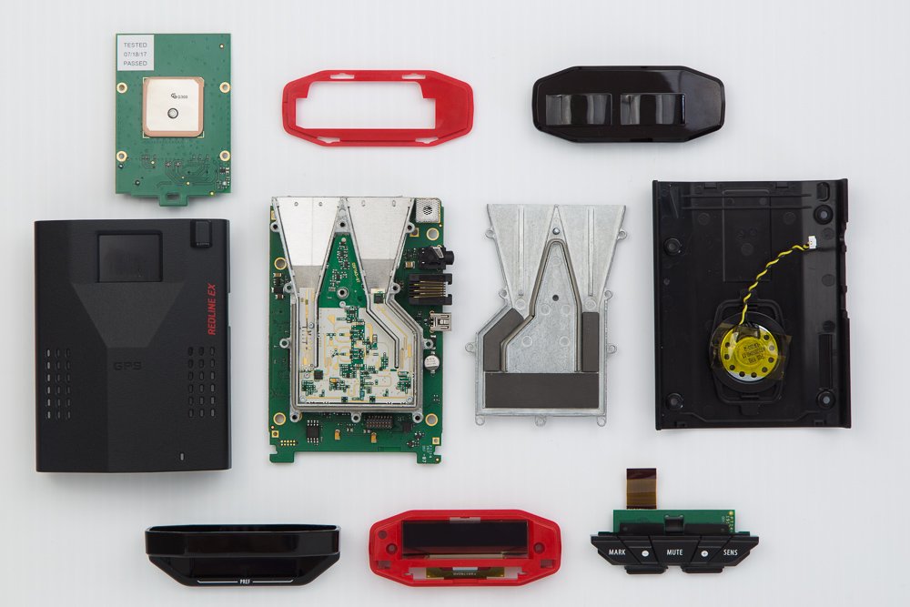
Let’s open up the new Redline EX and take a look at the Redline EX internals and see what’s going on under the hood. 🙂

Let’s start with the top of the detector:
Flipping it over, you’ll find 4 screws underneath to remove.
Take those off and the whole thing comes right apart. You’ve got the top and bottom covers as well as the condenser lens with a piece of red trim that comes right out.
One cool note is that the LED’s for the alert lamp are actually located on top of the detector. They aim upwards and then on the inside of the top of the case, there’s a white piece of plastic that catches the light, diffuses it, and redirects it forward for the alert lamp.
4 screws hold the GPS board with the alert lamp LED’s in place. Unscrew and carefully lift the GPS board out. (It’s connected via a series of pins near the display that reach down to the main board on the bottom.)
Once you do, you’ll be able to remove the display next. There’s two screws on either side of the display, holding it in place. Remove those and you’ll be able to pull off the display. There’s also two ribbon cables that you’ll need to release (pull up on the black tab), one for the display and another for the buttons.
(You can unscrew the display first, but you won’t be able to remove it until the GPS board is unscrewed which relieves tension holding the display on.)
and here’s the backside of the GPS board, main board, and display.
Let’s take a closer look at the main board.
The orange ribbon cable on the bottom connects the horn to the main board. We’re going to disconnect this ribbon cable so we can lift up the entire horn casing in a bit and look at the other side of the main board.
The two long white things at the bottom are where the ribbon cables for the display and buttons connect.
The big black chip on the right is the Redline EX’s microcontroller.
Here’s a closeup of the microcontroller.
For those of you who want some technical information, here’s the K20P144M100SF2V2 datasheet. (Thanks @FWGuy!)
Next let’s dive deeper and take a look at the horn and underlying circuitry.
First up is a look down the two horns. The one on the left handles X band detection. The one on the right handles K and Ka band detection.
Underneath the horns, behind the mesh, you can just make out the 4 laser detection diodes.
If we were to unscrew and pull the horn casing back from the main board, you’ll be better able to see the 4 laser detectors. Notice that two are pointed forward and two others are aimed off to the side.
The rear laser sensor is located in the silver box to the right of the forward facing laser sensors.
Here’s the top of the horn casing where the core of the detector is contained.
There’s a hidden screw underneath the sticker with all the different patents. I’m sure that Escort wants to make sure that anyone opening up their detectors (especially if they’re doing a teardown so that they can copy Escort’s design) knows that there’s a lot of patents that cover what you’re about to see here.
Here’s the internals of the Redline EX. The horn on the left handles K and Ka band detection while the horn on the right handles X band detection.
The design of the Redline EX (above) looks very reminiscent of the original M3 (below). For the sake of comparison, here’s a look at the internals of a Beltronics Magnum (with a packaged K/Ka LNA).
Anyway, let’s take a closer look at the internal circuitry of the Redline EX.
One thing I want to point out are the two different designed Low Noise Amplifiers (LNA’s). Looking at the photo below, the square box on the right, sitting right at the base of the horn, is the packaged LNA for X band.
At the base of the K/Ka horn on the left you’ll find a much smaller rectangular wire bonded LNA for K and Ka. It’s harder to apply a wire-bonded LNA as opposed to a packaged LNA, but all other things being equal, it leads to a performance gain of 2-3 dB so it’s a desirable feature in the interest of greater sensitivity and better performance.
Anyways, that’s a quick tour of the inside of a Redline EX!
If you’d like one for yourself, here’s where you can pick up the Redline EX:
USA: Click here to purchase the Redline EX. (Save $30 with the coupon code “escort30“)
Canada: Click here to purchase the Redline EX. (Save $25 with the coupon code “VortexRadar“)
| This website contains affiliate links and I sometimes make commissions on purchases. All opinions are my own. I don’t do paid or sponsored reviews.
Click here to read my affiliate disclosure. |
4 comments
Skip to comment form
Vortex,
Thank You for showing us. Can I ask you how you how I can get RJ11 to USB cord to plug in a portable charger?
Author
So I use one of these things https://geni.us/ShIfh that converts the cig. lighter cable into a USB port which I can then plug into a USB power source.
Great information! I was just wondering if you will be doing a teardown on the Uniden R3. I’m just curious to see the differences in Uniden’s R3 feed-horn design (packaged or not?) vs Escorts Redline EX’s.
Author
The R3 doesn’t actually have an LNA, interestingly enough. I’ve done a teardown on RDF https://www.rdforum.org/showthread.php?t=64646&page=4&p=904479&viewfull=1#post904479 but haven’t posted it here as well. I can post some info here too. I was able to get in and see the internals, but ultimately not get as deep as I had hoped. It’s tougher to get into all the guts of the R3.