Ka Guard and RDR are filters that help our radar detectors filter out false alerts on Ka band that happen due to poorly designed radar detectors like older Cobras that leak RF signals, but how do the filters actually work?
Escort has a patent explaining their filtering technique for RDR that I read through some time ago to learn the details of what’s actually going on under the hood. 🙂
Let’s take a look at the general idea behind how the filter works and then take a look at the science and math as we watch some sample signals actually make their way through the individual components of a radar detector.
The general idea is that when a radar detector is scanning for police radar, the local oscillator inside the detector that’s sweeping across different frequencies to help the radar detector scan across different frequencies as it looks for police radar, this LO actually emits RF energy that travels back up the RD and out the antenna, out to the outside world where it can be detected by radar detector detectors or other people’s radar guns. The harmonics of this leakage can happen to fall around the same frequencies as police radar which is what causes other radar detectors to false alert to Ka.
So any sort of Ka filter like RDR (Escort’s implementation) or Ka guard (Valentine’s implementation) is basically going to do an additional search to see if the Ka signal it’s detecting and considering alerting to is a harmonic that’s arising in the presence of another frequency signal that’s coming from an LO. If it is, that’s a false alert and it will filter that out. If there’s no LO present that’s creating this signal, which is how a police radar gun works, alert!
Now that we have the basic idea, let’s take a deeper level look at how it actually does this.
RDR under the hood
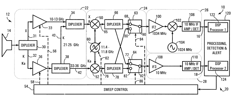
Here’s a schematic showing what goes on under the hood of the radar detector:

It may look a bit complicated at first, but there’s a few distinct sections that we’ll walk through step by step in a moment and it’ll become quite simple.
Now first off, the detector can’t scan the entire frequency range instantly. It has to progressively sweep over the entire radar frequency spectrum over and over and over looking for a signal. You’ll see the sweep controller (54) at the very bottom of the schematic that controls where and when it sweeps specific frequencies and radar bands.
The received radar signal comes in from the antenna (14) on the left. This design shows the the received signal being split through a diplexer (30) so it can do separate X, K, and Ka band sweeps.
Each of the three bands one then mixed in with the local oscillator (60) one at a time. In this patent, they discuss an LO oscillating at 11.5583 GHz. You know how in music we have different musical octaves? Go up one octave and you double the frequency. In the case of RD’s, the original frequency is called the fundamental frequency. Doubling the frequency would be the first harmonic. The next step up would be the second harmonic, and so on.
Fundamental frequency: 11.5583 GHz
1st harmonic: 23.1166 GHz
2nd harmonic: 34.6749 GHz
Have you noticed how each frequency just so happens to be very close to each of the 3 police radar bands? Not exact, but close. This is key.
X band: 10.5-10.55 GHz
K band: 24.05-24.25 GHz
Ka band: 33.4-36.0 GHz
If we subtract the difference between the harmonic and the detected frequency, that difference is called the intermediate frequency, the IF.
Note that all of the IF’s are going to be in the ~1 GHz ballpark, particularly with X band and K band.
ie. 11.5 GHz – 10.5 GHz = 1 GHz.
24.1 GHz – 23.1 GHz = 1 GHz.
Since Ka band has a wider frequency bandwidth, the IF will vary more.
Anyways, if we then mix this ~1 GHz signal in with a second LO that’s oscillating at 1 GHz, we can step the signal down once again to a lower frequency (the second IF) that’s much easier to process. At this stage, we’re looking at X and K band signals that will typically have been stepped down closer to the 10 MHz range which are much much easier to analyze.
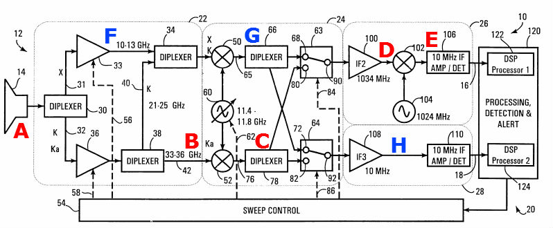
Let’s take another look now back at the circuit schematic, this time labeled for each stage.

Let’s look at the red labels and trace through a Ka signal. For the sake of this example, let’s say we’re working with a 33.7 GHz signal which could potentially be either an MPH Bee III or a Cobra.
A) Received Ka signal
B) Ka signal gets separated away from the X and K band and heads towards the first LO.
C) The Ka signal is mixed with the LO’s third harmonic to come up with an IF frequency. (34.6749 – 33.7 = 0.9749 GHz or 974.9 MHz)
D) The signal then gets mixed in with a 1024 MHz LO to step it down even further. (1024 MHz – 974.9 MHz = 49.1 MHz)
E) This 49.1 MHz signal then gets amplified and then sent into the signal processor. If there’s a strong enough signal to be detected, the detector has found a signal that it can alert to.
If RDR is turned off, it’ll alert to this signal without any further processing. It found a Ka signal and will immediately alert to it.
But now what if RDR is turned on? If this is the case, the detector is going to do another sweep and check for LO leakage. If you look back at the schematic, you’ll see the LO frequency for this detector varies somewhere between 11.4 – 11.8 GHz (11.5583 in this example). In the case of a detected 33.7 GHz false, that would be the third harmonic of a leaky 11.233 GHz LO. That’s in the ballpark of an X band signal so if we do a sweep for an X band signal at 11.233 GHz and we find something, then we know that 33.7 GHz signal is a harmonic of a leaky 11.233 GHz LO and thus we have a Cobra false.
Let’s see how this signal is scanned for, this time by following the blue labels.

F) The received signal comes in through the antenna and gets passed up into the X band region of the detector.
G) The received frequency gets mixed in with our LO once again to create an IF. (11.5583 – 11.233 GHz = 0.3253 GHz or 325.3 MHz)
H) This signal is already a low enough frequency that it doesn’t have to be stepped down again to get out of the GHz range, so it can pass directly into a different amplifier and a second signal processor.
This second signal processor looks for a detected signal. If a signal is detected here, then we’ve detected the presence of a leaky LO.
To double check, we can do a K band sweep and look for the presence of a second harmonic at 11.233 * 2 = 22.466 GHz. If we detect a signal at this frequency, this confirms what we found with our X band sweep for the first harmonic.
Cobra false detected! Don’t alert.
Finishing Up
So that’s how RDR in Escort products work. I haven’t gone searching for information on Valentine’s implementation of Ka guard and so the way they do it may happen to be a bit different, but the general principle of searching for harmonics and fundamental frequencies is the same. 🙂
| This website contains affiliate links and I sometimes make commissions on purchases. All opinions are my own. I don’t do paid or sponsored reviews. Click here to read my affiliate disclosure. |


1 comments
Hello. Is there a clear diagram of the circuit